Hardware Assembly
Minimal Documentation
The build guide for assembling the Ender 5 Mint Edition is fairly minimal, and assumes you have a basic knowledge of how a 3D printer works. It will walk through basic wiring for the main power (mains, 24v, and 48v) but will not help you much past that.
If you need more in-depth direction to how electronics are mounted in the enclosure, please refer to the Fusion CAD on Gettting Started
If you do not know how to connect a custom mainboard to a printer, or are intimidated by this message, do not continue past this warning
Electronics Enclosure
Printed Parts
The electronics enclosure is printed in 6 parts (refer to the BOM).
-
The main parts are simply screwed together with M3x6 SHCS from the center piece into the 8 joints between the pieces, no nuts or inserts needed:
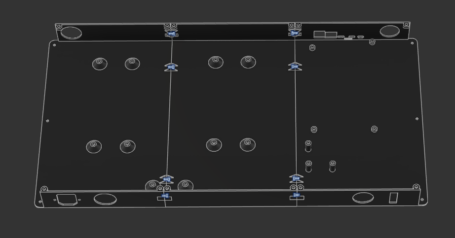
-
M3x5x4 heat-set inserts are inserted into the main shell for mounting the mesh and a few electronics:
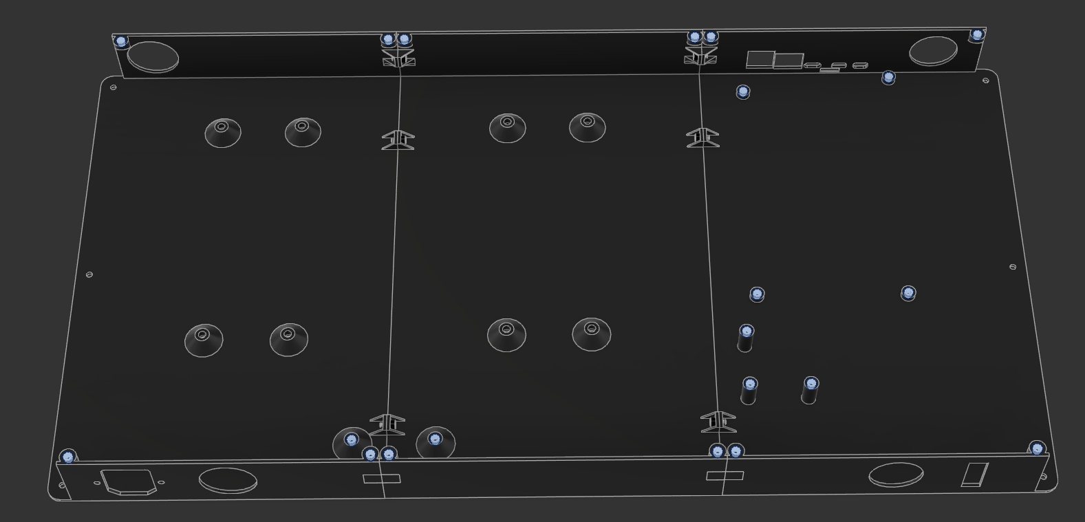 \
\ -
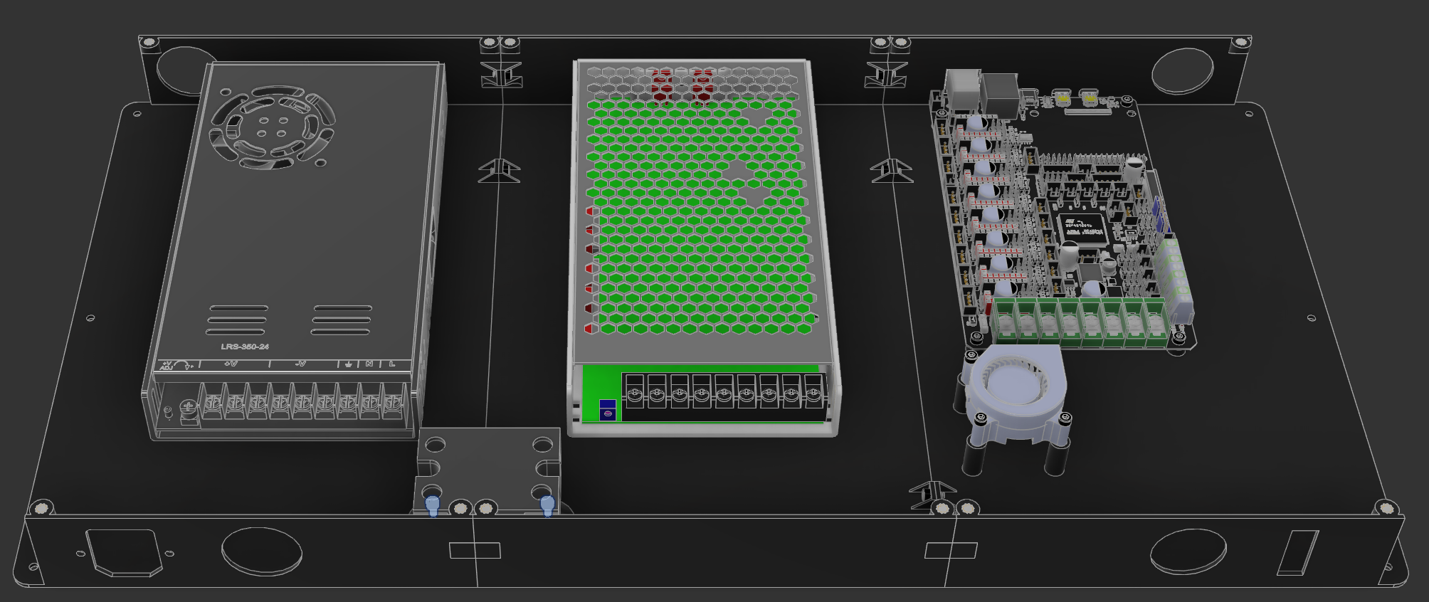
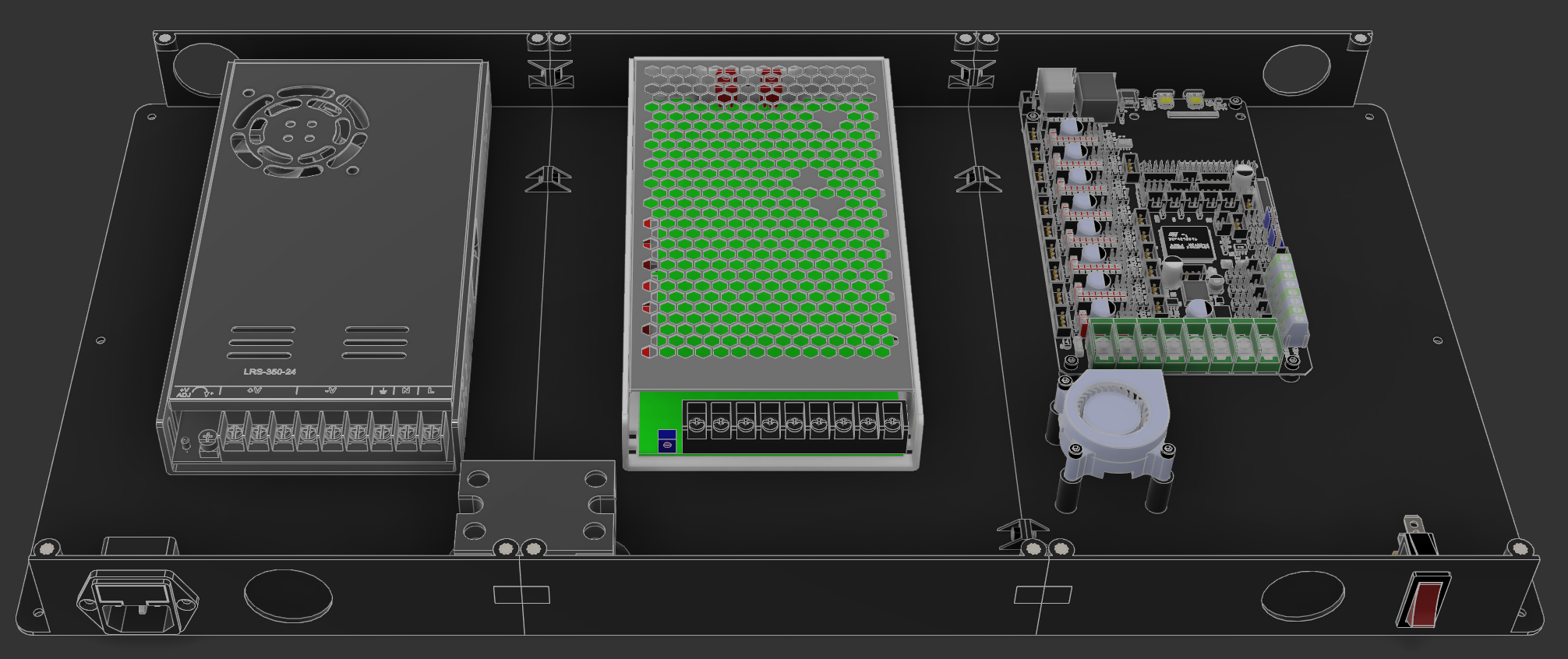
Mount the M8P using 4 M3x4 SHCS:
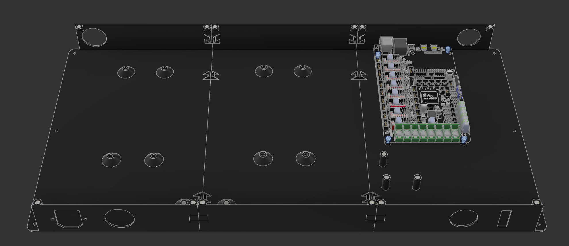
-
Mount the power supplies (or singular power supply) using M4x8 SHCS:

-
Mount the 4020 blower fan to the 3 raised standoffs using M3x16 SHCS:
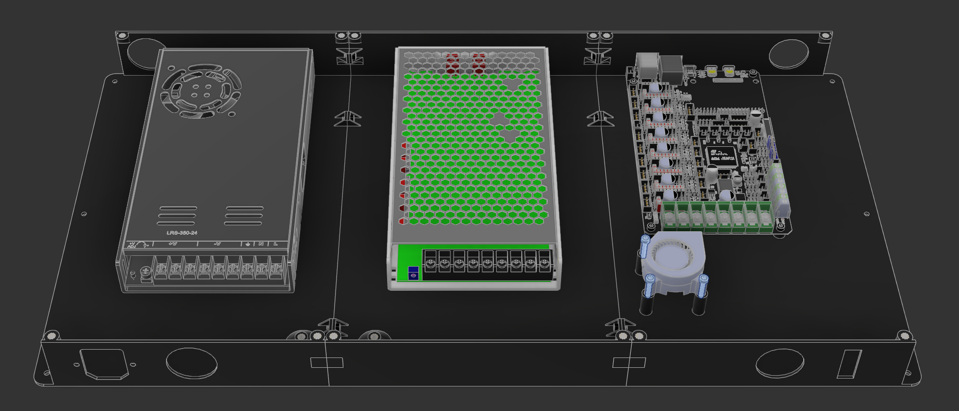
-
Mount the SSR to the small standoffs between the power supplies using M3x6 SHCS:
-
Mount the KCD rocker switch gold pin towards the bottom and the IEC C14 fuse plug. The plug uses 2 M3x8 countersunk screws:
-
Mount the electronics enclosure in place of the original enclosure, using M3x6 SHCS. No pictures for this step

- Using the 4 M4x35 SHCS, mount the feet extensions to the bottom of the printer, re-using the original rubber feet and washer for vibration dampening
- Using 8 M3x16 SHCS and 8 M3 nuts, mount the 4010 axial fans to the M8P mesh part. There are specific mounting holes for these. Make sure the blades will pull air into the enclosure!
Wiring
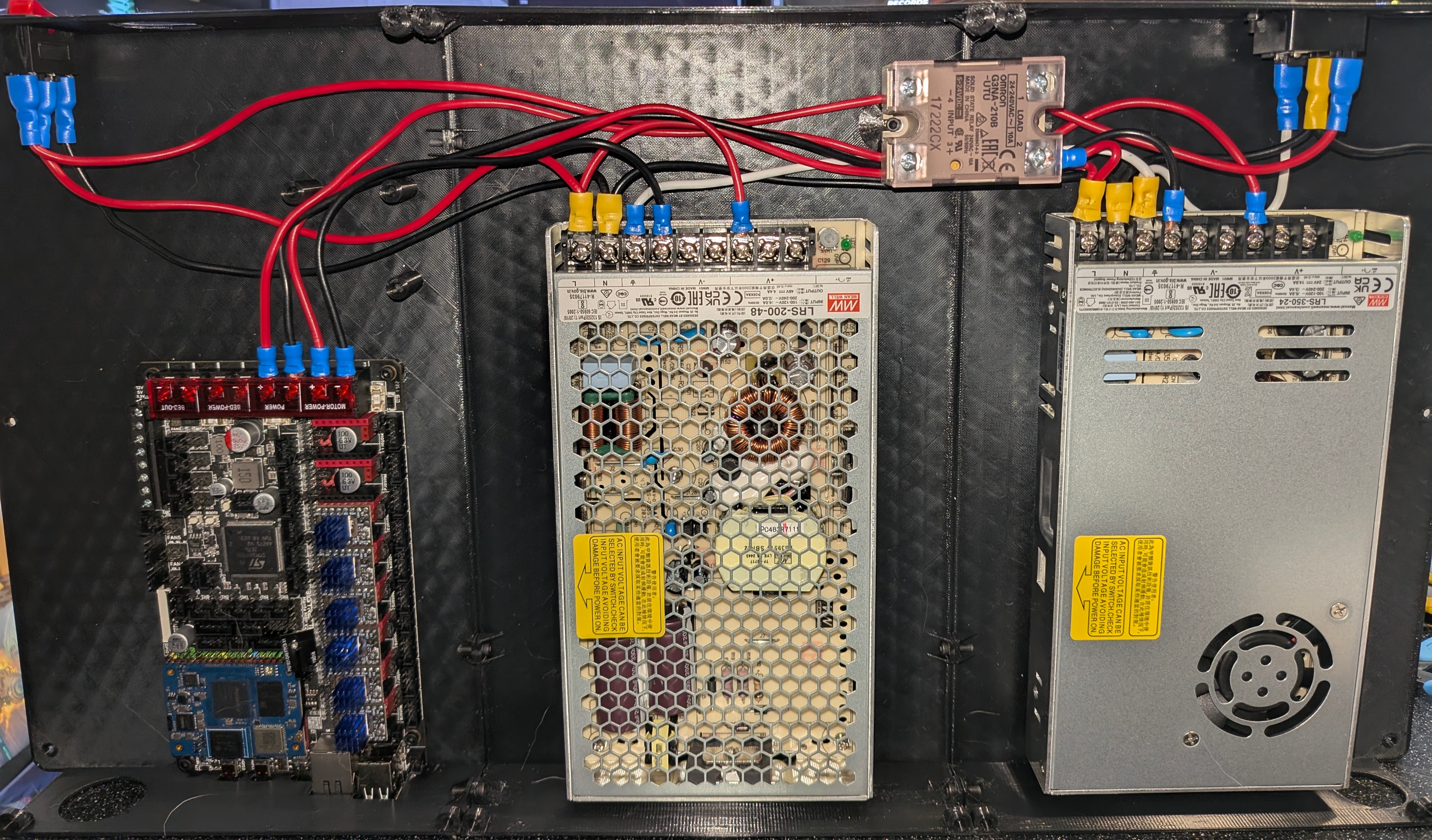
Wire everything together! Refer to the picture and to the diagram for more information:
Mains
| Source | Destination | Color | Multiple Crimp at Destination |
|---|---|---|---|
| IEC 14 Top | KCD Rocker Top | Red | No |
| KCD Rocker Middle | LRS-200-48 Live (L) | Red | Yes |
| LRS-200-48 Live (L) | LRS-350-24 Live (L) | Red | Yes |
| LRS-350-24 Live (L) | SSR Port 2 | Red | No |
Ground
| Source | Destination | Color | Multiple Crimp at Destination |
|---|---|---|---|
| IEC 14 Bottom | LRS-350-24 Ground (⏚) | White | Yes |
| LRS-350-24 Ground (⏚) | LRS-200-48 Ground (⏚) | White | No |
Neutral
Add 2 wires at IEC 14
We need two wires coming from the IEC 14 plug. One will go to the bed directly, and the other will follow the diagram below
| Source | Destination | Color | Multiple Crimp at Destination |
|---|---|---|---|
| IEC 14 Middle | LRS-350-24 Neutral (N) | Black | Yes |
| LRS-350-24 Neutral (N) | LRS-200-48 Neutral (N) | Black | Yes |
| LRS-200-48 Neutral (N) | KCD Rocker Bottom | Black | Yes |
24V V+ and V-
| Source | Destination | Color | Type |
|---|---|---|---|
| LRS-350-24 V+ | M8P Power + | Red | V+ |
| LRS-350-24 V- | M8P Power - | Black | V- |
48V V+ and V-
Voltage Difference
Make sure that your 24V and 48V lines do not cross! You will destroy components if you do so!
You have been warned
| Source | Destination | Color | Type |
|---|---|---|---|
| LRS-200-48 V+ | M8P Motor Power + | Red | V+ |
| LRS-200-48 V- | M8P Motor Power - | Black | V- |